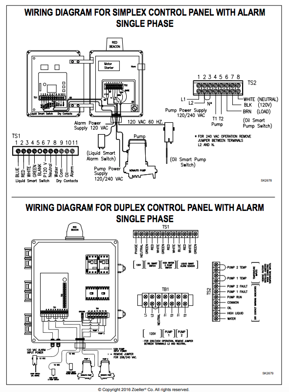
Zoeller Well Pump Control Box Wiring Diagram
Https Www Manualshelf Com Manual Zoeller 1451 0007 How To Guide English Spanish Html

Zoeller Steel Control Box In The Water Pump Accessories Department At Lowes Com

Zoeller 10 2338 Control Box For 3 Wire Potable Water Turbine Pump Series 452 1 Hp

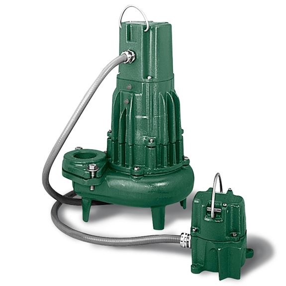
Zoeller 842 0008 Model G842 Shark Series Grinder Pump 2 Hp 460 Volts 3 Phase 1 1 4 Npt Discharge 32 Gpm Max 125 Ft Max Head 20 Ft Cord Manual
Zoeller Potable Water Turbine Pumps Buyers Guide Review

Pin On Hydraulics Pneumatics And Pumps

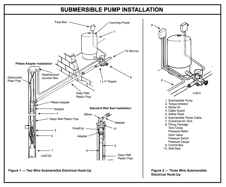
2 wire well pump diagrams are slightly easier to understand and are more straight forward to wire.
Zoeller well pump control box wiring diagram.

Zoeller 10 1494 Manual Reset Indoor High Water Alarm 115 Vac Plumbing Planet High Water Alarm Vac
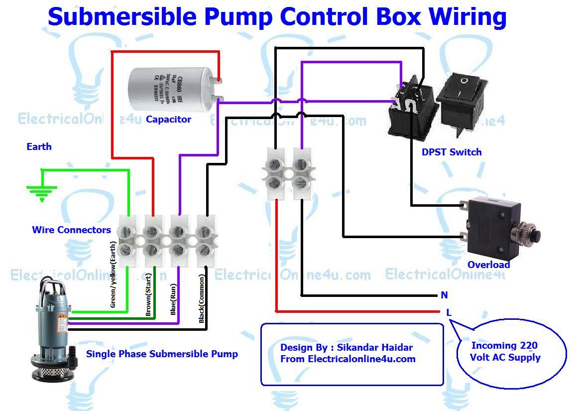
Diagram Zoeller Submersible Pump Wiring Diagram Full Version Hd Quality Wiring Diagram Free0g K Danse Fr

Zoeller 120 Drainage Pump System With Polypropylene Basin Lid
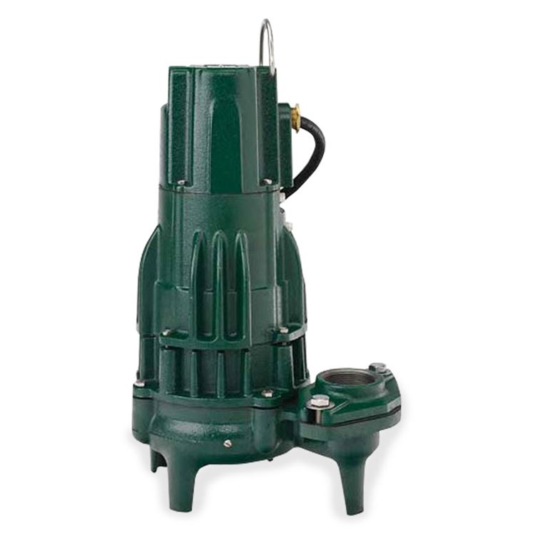
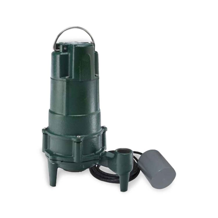
Zoeller Zoeller 818 0007 Model Wd818 Shark Single Directional Grinder Pump 1 0 Hp 230v 1ph 20 Cord Automatic Zlr818 0007
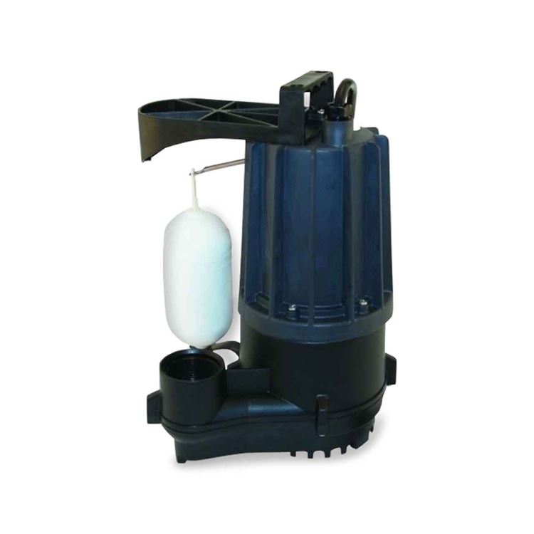
Zoeller Zoeller 57 0004 Model E57 Sump Effluent Pump 0 33 Hp 230v 1ph 15 Cord Nonautomatic Zlr57 0004

Zoeller 0 5 Hp 230 Volt Stainless Steel Submersible Well Pump In The Water Pumps Department At Lowes Com
Zoeller Zoeller 3163 0002 Model N3163 High Temperature Submersible Pump 0 5 Hp 115v 1ph 20 Cord Nonautomatic Zlr3163 0002

Zoeller 161 0001 Model M161 Submersible Pump 1 2 Hp 115 Volts 1 Phase 15 5 Amps 1 1 2 Discharge 100 Gpm Max 56 Ft Max Head 20 Ft Cord Automatic
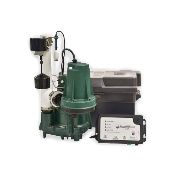
Zoeller Zoeller 508 0007 Aquanot Spin 508 M98 Propak Battery Backup System 12vdc Zlr508 0007

Pin On Hydraulics Pneumatics And Pumps
Zoeller 294 1 5 Hp 230v High Head Sewage Dewatering Pump

1hp Electric Plastic Submersible Water Pump Motor Prices In India Water Pump Motor Electric Water Pump Submersible
Zoeller Oil Guard Systems Buyers Guide Review Pumpproducts Com
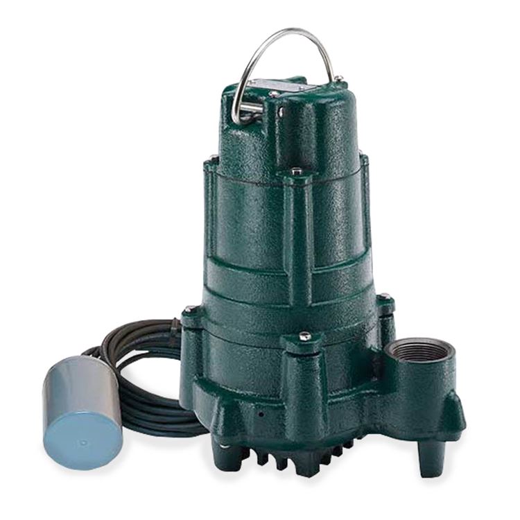
Zoeller Zoeller 76 0001 Model M76 Dewatering Pump 0 5 Hp 115v 1ph 9 Cord Auto Zlr76 0001

Zoeller 507 0005 Basement Sentry Battery Backup Sump Pump Review Http Sumppumpsrus Com Zoller 507 0005 Backup Sump Pump Battery Backup Sump Pump
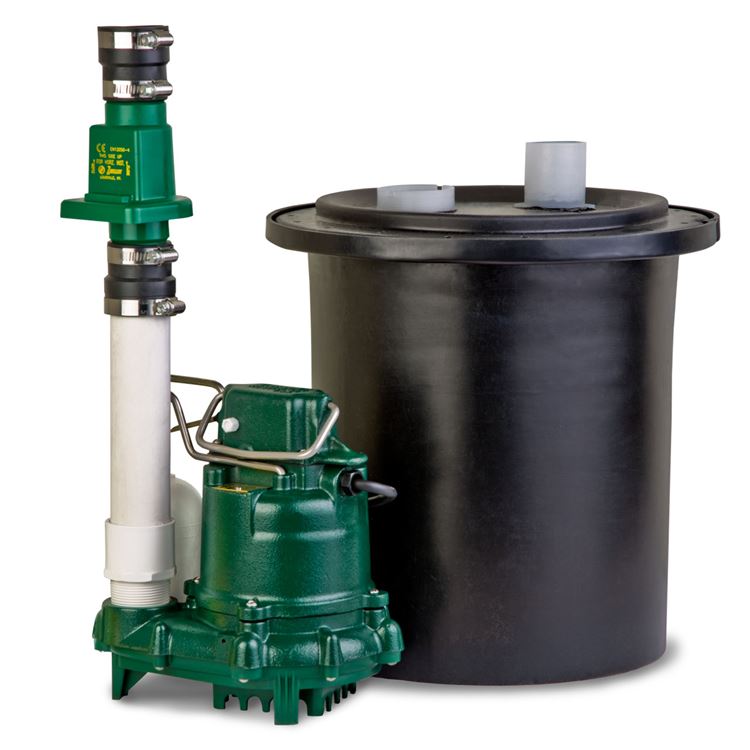
Zoeller Zoeller 105 0010 Model 105 Preassembled M53 Drain Pump System With Polypropylene Basin Lid Zlr105 0010
Zoeller Zoeller 807 0005 Model Bn807 Shark Fractional Hp Grinder Pump 1 0 Hp 115v 1ph 15 Cord Automatic Zlr807 0005

Zoeller 3163 0001 Model M3163 High Temperature Submersible Pump 0 5 Hp 115 Volts 1 Phase 1 1 2 Discharge 53 Gpm 5 Ft 3 Ft Conduit Automatic 15 Ft Cord 1 1 2 Discharge

Best Water Powered Sump Pump Reviews And Buying Guide
Zoeller Zoeller 140 0005 Model Bn140 Sump Effluent Pump 1 0 Hp 115v 1ph 20 Cord Automatic Zlr140 0005

Le71m2 Liberty Le71m2 3 4 Hp Manual Submersible Sewage Pump 115v 10 Ft Cord 2 Discharge Sewage Pump Sewage Pumps Submersible

Zoeller 461 0006 Model Ne461 Shallow Well Jet Pump 3 4 Hp 115 230 Volts 1 Phase 1 1 4 Suction 3 4 Discharge Cast Iron Body

Zoeller 452 0007 4 Deep Well Submersible Pump And Motor With Leads 19 Gpm 1 Hp 230 Volts 1 Phase 3 Wire 9 Stages 1 1 4 Discharge

7803ec9c552290edcd585acf4af54f02 Jpg Deep Well Pump Submersible Pump Well Pump
Source : pinterest.com
